- 您现在的位置:买卖IC网 > Sheet目录3873 > PIC18F45K20-I/MV (Microchip Technology)MCU 32KB FLASH 1536B RAM 40-UQFN
2007 Microchip Technology Inc.
Preliminary
DS70165E-page 85
dsPIC33F
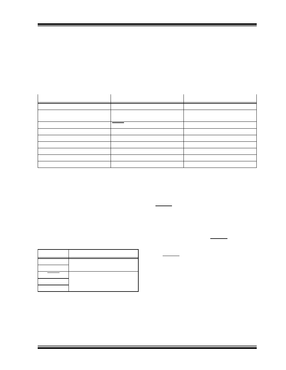
TABLE 5-1:
RESET FLAG BIT OPERATION
5.1
Clock Source Selection at Reset
If clock switching is enabled, the system clock source at
device Reset is chosen, as shown in Table 5-2. If clock
switching is disabled, the system clock source is always
selected according to the oscillator Configuration bits.
Refer to Section 8.0 “Oscillator Configuration” for
further details.
TABLE 5-2:
OSCILLATOR SELECTION vs.
TYPE OF RESET (CLOCK
SWITCHING ENABLED)
5.2
Device Reset Times
The Reset times for various types of device Reset are
summarized in Table 5-3. The system Reset signal,
SYSRST, is released after the POR and PWRT delay
times expire.
The time at which the device actually begins to execute
code also depends on the system oscillator delays,
which include the Oscillator Start-up Timer (OST) and
the PLL lock time. The OST and PLL lock times occur
in parallel with the applicable SYSRST delay times.
The FSCM delay determines the time at which the
FSCM begins to monitor the system clock source after
the SYSRST signal is released.
bit 0
POR: Power-on Reset Flag bit
1
= A Power-up Reset has occurred
0
= A Power-up Reset has not occurred
Flag Bit
Setting Event
Clearing Event
TRAPR (RCON<15>)
Trap conflict event
POR
IOPUWR (RCON<14>)
Illegal opcode or uninitialized
W register access
POR
EXTR (RCON<7>)
MCLR Reset
POR
SWR (RCON<6>)
RESET
instruction
POR
WDTO (RCON<4>)
WDT time-out
PWRSAV
instruction, POR
SLEEP (RCON<3>)
PWRSAV #SLEEP
instruction
POR
IDLE (RCON<2>)
PWRSAV #IDLE
instruction
POR
BOR (RCON<1>
BOR
—
POR (RCON<0>)
POR
—
Note:
All Reset flag bits may be set or cleared by the user software.
REGISTER 5-1:
RCON: RESET CONTROL REGISTER(1)
Note 1:
All of the Reset status bits may be set or cleared in software. Setting one of these bits in software does not
cause a device Reset.
2:
If the FWDTEN Configuration bit is ‘1’ (unprogrammed), the WDT is always enabled, regardless of the
SWDTEN bit setting.
Reset Type
Clock Source Determinant
POR
Oscillator Configuration bits
(FNOSC<2:0>)
BOR
MCLR
COSC Control bits
(OSCCON<14:12>)
WDTR
SWR
发布紧急采购,3分钟左右您将得到回复。
相关PDF资料
PIC16CR76T-I/SS
IC PIC MCU 8KX14 28SSOP
PIC18F13K50-I/P
IC PIC MCU FLASH 4KX16 20-PDIP
PIC16CR76T-I/SO
IC PIC MCU 8KX14 28SOIC
PIC18LF24K22-I/MV
IC PIC MCU 16KB FLASH 28UQFN
PIC18LF24K22-I/ML
IC PIC MCU 16KB FLASH 28QFN
PIC16CR76T-I/ML
IC PIC MCU 8KX14 28QFN
PIC16F627-04/P
IC MCU FLASH 1KX14 COMP 18DIP
PIC18F45J10-I/ML
IC PIC MCU FLASH 16KX16 44QFN
相关代理商/技术参数
PIC18F45K20-I/P
功能描述:8位微控制器 -MCU 32KB Flash 1536B RAM 25 I/O 8B RoHS:否 制造商:Silicon Labs 核心:8051 处理器系列:C8051F39x 数据总线宽度:8 bit 最大时钟频率:50 MHz 程序存储器大小:16 KB 数据 RAM 大小:1 KB 片上 ADC:Yes 工作电源电压:1.8 V to 3.6 V 工作温度范围:- 40 C to + 105 C 封装 / 箱体:QFN-20 安装风格:SMD/SMT
PIC18F45K20-I/PT
功能描述:8位微控制器 -MCU 32KB Flash 1536B RAM 25 I/O 8B RoHS:否 制造商:Silicon Labs 核心:8051 处理器系列:C8051F39x 数据总线宽度:8 bit 最大时钟频率:50 MHz 程序存储器大小:16 KB 数据 RAM 大小:1 KB 片上 ADC:Yes 工作电源电压:1.8 V to 3.6 V 工作温度范围:- 40 C to + 105 C 封装 / 箱体:QFN-20 安装风格:SMD/SMT
PIC18F45K20T-I/ML
功能描述:8位微控制器 -MCU 32KB Flash 1536B RAM 25 I/O 8B RoHS:否 制造商:Silicon Labs 核心:8051 处理器系列:C8051F39x 数据总线宽度:8 bit 最大时钟频率:50 MHz 程序存储器大小:16 KB 数据 RAM 大小:1 KB 片上 ADC:Yes 工作电源电压:1.8 V to 3.6 V 工作温度范围:- 40 C to + 105 C 封装 / 箱体:QFN-20 安装风格:SMD/SMT
PIC18F45K20T-I/MLV01
制造商:Microchip Technology Inc 功能描述:
PIC18F45K20T-I/MV
功能描述:8位微控制器 -MCU 32KB FL 1536b RAM 8b Familynanowatt XLP
RoHS:否 制造商:Silicon Labs 核心:8051 处理器系列:C8051F39x 数据总线宽度:8 bit 最大时钟频率:50 MHz 程序存储器大小:16 KB 数据 RAM 大小:1 KB 片上 ADC:Yes 工作电源电压:1.8 V to 3.6 V 工作温度范围:- 40 C to + 105 C 封装 / 箱体:QFN-20 安装风格:SMD/SMT
PIC18F45K20T-I/PT
功能描述:8位微控制器 -MCU 32KB Flash 1536B RAM 25 I/O 8B RoHS:否 制造商:Silicon Labs 核心:8051 处理器系列:C8051F39x 数据总线宽度:8 bit 最大时钟频率:50 MHz 程序存储器大小:16 KB 数据 RAM 大小:1 KB 片上 ADC:Yes 工作电源电压:1.8 V to 3.6 V 工作温度范围:- 40 C to + 105 C 封装 / 箱体:QFN-20 安装风格:SMD/SMT
PIC18F45K22-E/ML
功能描述:8位微控制器 -MCU 32KB Flash 1536B RAM 8B nanoWatt RoHS:否 制造商:Silicon Labs 核心:8051 处理器系列:C8051F39x 数据总线宽度:8 bit 最大时钟频率:50 MHz 程序存储器大小:16 KB 数据 RAM 大小:1 KB 片上 ADC:Yes 工作电源电压:1.8 V to 3.6 V 工作温度范围:- 40 C to + 105 C 封装 / 箱体:QFN-20 安装风格:SMD/SMT
PIC18F45K22-E/MV
功能描述:8位微控制器 -MCU 32KB 1536b RAM 8bit familynanoWatt XLP RoHS:否 制造商:Silicon Labs 核心:8051 处理器系列:C8051F39x 数据总线宽度:8 bit 最大时钟频率:50 MHz 程序存储器大小:16 KB 数据 RAM 大小:1 KB 片上 ADC:Yes 工作电源电压:1.8 V to 3.6 V 工作温度范围:- 40 C to + 105 C 封装 / 箱体:QFN-20 安装风格:SMD/SMT